The Sentinel Rebreather
The Sentinel Rebreather Concept Description
|
The Sentinel Rebreather Concept Description |
|
||||
|
|
|||||
|
I decided to put this together based on comments and
observations at the last two dive shows.
Why did I design the Sentinel (S) and how does it differ from
the Ouroboros (OR).
The OR will always be our deep diving rebreather. It has very
low breathing resistance (resistive), great electronics and
manual backup systems and a virtually fail-safe gas plumbing
system (Swagelok 316 stainless). All of these things add cost
(especially the Swagelok!).
95% of divers will never take this rebreather anywhere near its'
performance limits.
My view is that recreational diving now regularly takes a lot of
people to 100m. This has led to the new design. Ten years ago
100m diving was heavy-duty expedition territory, now it is not.
100m as a bailout (with reasonable bottom times) is also not too
difficult logistically.
So the challenge is to make a rebreather more cost effectively
but still with an acceptable (and high) degree of performance.
Breathing Performance
Breathing performance should never be compromised in
life-support equipment and it is continually a balance between
low overall work of breathing and the size of the unit (in
particular the mouthpiece).
A unit that will always be used by very experienced divers, that
never get stressed, can arguably have a lower breathing
performance. A unit designed for a spectrum of the general
diving market must assume stress will occur and when it does, if
breathing performance is poor, the safety of the diver will be
compromised.
The energy expended by a diver to push gas around a rebreather
is a combination of three primary things.
1. The resistance to flow of all the bores within the unit
(houses, mouthpiece etc.). At the surface as a diver breathes
out and in again a breathing performance analyser will show a
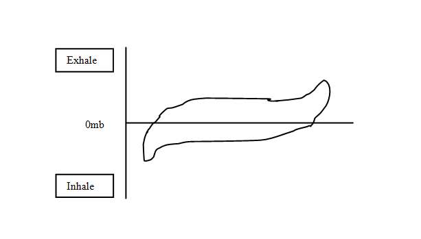
rise and then fall in pressure throughout the breathing cycle.
This is known as the Pressure/Volume diagram or PV diagram. At
the surface it is a sideways ellipse about zero pressure, much
like the shape of your eye. The area within this ellipse is
measured in Joules/liter and is known as the Resistive
Effort (RE) required to push gas around the breathing circuit.
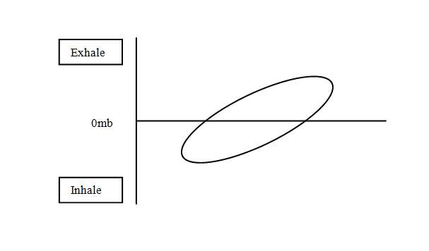
At depth with increased gas density this ellipse will fatten,
increasing the Joules/liter. An increase in breathing rate also
increases the joules/liter. |
|||||
|
|
|||||
|
If the counterlung you are breathing into is too small for a
standard breath, the two ends of the ellipse will turn up and
down respectively. Further degrading the 'breathing feel' and
increasing the peak to peak pressure felt by the diver.
|
|||||
|
|
|||||
|
A low RE is essential in any rebreather design as the effects of
it cannot be compensated for by the diver, it is purely a
function of the mechanics of the rebreather.
2. Once the unit is submerged, hydrostatic effect now plays a
part. Depending on the test position (vertical or horizontal),
the shape of the counterlungs (long/thin Vs doughnut etc.) and
their position in the set will affect the angle of the ellipse.
The ellipse, previously about zero, will tilt up to add a
minimum and maximum peak pressure to the PV ellipse. These peak
to peak pressures also affect 'breathing feel'. If the
Counterlungs (CL ) are long and this and the unit is anywhere
other than horizontal the PV will start to angle up
considerably, again degrading the 'b
reathing feel'. |
|||||
|
|
|||||
|
A CL of a safe minimum size (so as not to affect 1 above),
shaped around the centroid position of the divers lungs will
produce lower peak to peak pressures. Both this and the RE are
tested at depth with high ventilation rates, as again the diver
can do nothing to correct these issues in set design except
breathe slower.
Hence the results from 1 and 2 are additive and go towards
the total 'breathing feel' of the unit.
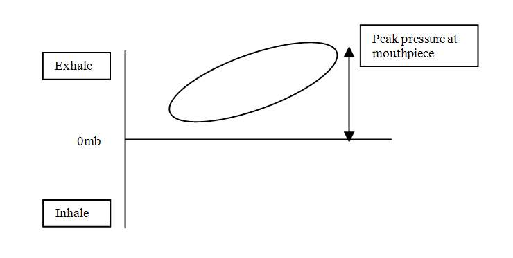
3. A final function is important and that is the Rotational
Hydrostatic Effect (HE). This simulates the diver moving into
different positions. It is function of 1 and 2 above and the
counterlung position (and shape) with reference to lung centroid
in these varying positions. It is currently conducted with a
fixed loop volume so that comparisons can be drawn. The rotation
has the effect of moving the angled PV diagram up and down about
the zero point (and in some cases modifying the angle) and in
effect creating an offset (addition/subtraction) in peak
pressure. |
|||||
|
|
|||||
|
So for the total 'breathing feel' of a set, 1,2 and 3 are all
added together at this stage. Test 3 gives the only result where
the diver has the ability to compensate for the pressures seen
at the mouthpiece as they can vent or inject manually in the
different positions or change position, thus improving the
'feel' somewhat.
Units with overshoulder counterlungs generally have a lower HE.
But if counterlung volumes are excessive or are not constrained,
the HE results can be compromised significantly.
Backmounted counterlungs traditionally show high HE when the
diver is swimming on their back.
So given that the total breathing feel of a set is a function of
all three of the above, almost any CL concept can be made to
generate a good overall work of breathing. Well designed
over-shoulder counterlungs traditionally solve the HE problem
quite well but designs often compromise items 1 and 2 as a
result, which remain un-adjustable by the diver.
Over-shoulder CL's have their own issues such as 'harness
clutter' and large buoyancy shifts, which can in-turn affect the
sets ability to track PO2 setpoint accurately. |
|||||
|
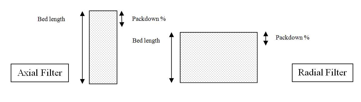
Absorbent Filters
Traditionally we have been led to believe that axial designs are
a low-duration performer and radial is high. This is not always
the case. What can be said is that radial designs have a lower
breathing resistance due to the bed length and are often less
prone to packing errors due to the bed height versus the pack
down % (at least in doughnut radials). |
|||||
 |
|||||
|
Axial canisters can be just as efficient.
The Sentinel can uses a granular (Sofnolime 797) user packed
absorbent system. This interfaces to three absorbent monitoring
systems (later).
Counterlung
The unit comes as standard with one back-mounted counterlung
(CL). This CL is teed off of the inhale side of the loop at the
output of the canister head, hence the inhale breathing hose is
not actually connected to it, it is just provides an expandable
volume. In a head-down position water will preferentially drain
into the CL. When the diver goes head-up again, water drains
back to the canister base where the water/gas dump is
positioned.
The single back-mounted CL has several advantages;
1. More protection
2. Less heat loss
3. Simpler flood recovery
4. Reduction of failure points
A second option is now available for the Sentinel, the Travel
Kit. The set will be available without its' hard case. A range
of cylinders sizes can attach to a fold-flat back plate. To this
you can attach and BC/Harness.
This configuration will allow the diver to travel with a
small/lighter set. |
|||||
|
Gas systems
The set has no high-pressure (HP) hoses. It uses digital HP
sensors fitted directly into the first stage. The digital
HP provides content and usage/leak alarms.
The set uses the same oxygen solenoid as the Ouroboros. It is
rated to over 15 bar as an interstage pressure. The regulator
first stages can be either Poseidon or Apeks with a 12 bar
(approx.) over pressure valve (OPV), primarily to protect the
solenoid and low pressure (LP) piping.
The LP circuit does not use conventional hoses. It uses
super-flexible LP tubing with a woven protective cover with a
burst pressure of 200 bar. The tubing is more resilient to UV
and saltwater in long-term use than rubber. It is also lighter
and more flexible.
The Expedition version of the sentinel comes with an off-board
gas connector (Swagelok) fitted to each block. This system is
unique in that it not only allows off-board gas to be injected
manually but it also routes it through the automation (ADV,
solenoid). The diluent off-board is even available at the
Bailout Valve (BOV).
The BOV is integrated into the mouthpiece (which is neutral
in-water). Simply rotating the switch selects open or closed
circuit. |
|||||
|
The BOV is used as a 'sanity' breath system. This is especially
useful in hypercapnic incidents where there is a strong desire
NOT to switch off the set to an alternative bailout regulator.
The 'sanity breath' allows you to asses the situation and then
take the correct action.
The BOV and breathing hoses are counterweighted to offset
buoyancy.
The breathing hoses are fitted to the canister head via a dual
lock quick-release system, compromising a quarter-turn and a
push button. The hose ends are double radial O-ring sealed. The
complete mouthpiece and hose assembly can be quickly removed for
cleaning as can the CL.
The diluent LP circuit is fed from the first stage through a
multi-port manifold to allow connection of BCD/suit feeds etc.
The HP sensors use a 'dynamic reserve' system. On the diluent
side, dependant on depth and an assumption of open-circuit
breathing rate, the reserve alarm will vary. Hence in shallow
water the alarm will trigger later compared to deep water, still
allowing a safe ascent to the surface.
Oxygen setpoint control is also dynamic. The set can be put in
'auto-setpoint' mode. PO2’s for bottom-mix and decompression-mix
are adjustable over a range.
Upon submersion the unit will slowly increase the setpoint to
the preset during the descent. Once at a stable depth the diver
can select the high setpoint themselves or wait until the set
automatically switches.
Upon ascent the set will remain at the high setpoint until the
safety or required decompression is complete and then decrement
towards the surface (reducing to 0.7) to avoid unnecessary
buoyancy shifts.
The loop over-pressure valve is located in the canister base. It
is also the water drain. It is unique in that it can be set on
the surface for a given pressure and then irrespective of the
position of the diver in the water, it will always dump at
approximately the same pressure.
The set comes with dual 2l cylinders. As the base foot of the
case is extendable (or removable) longer cylinders of a similar
diameter can be fitted. As the 1st stages are free to move,
almost any style of cylinder valve can be fitted. The standard
valve supplied is an AP Diving cylinder valve. |
|||||
|
Electronics
The unit comes with electronics similar to the Ouroboros with a
different human-computer interface (HCI).
There are two HUD's, one front and one rear. A Primary display
and a Backup display.
All the electronics, solenoid and batteries are outside of the
breathing loop.
The Primary display connects to the Core Life-Support Module in
the canister head via a cable. The Primary does not contain any
system control electronics and is just a display. The Core
Module provides life-support and decompression status.
The HUD's, Backup display and HP sensors also connect into the
Core Module.
Electronic failure of any display will not affect life-support
functionality.
The HUD on a level one unit has 3 states.
Green - All OK
Amber - Your consumables are running low, slowly ascend towards
the surface on closed circuit (often this alarm will go away on
ascent.
Red - Perform open circuit bailout now. You will then be
prompted to switch the Primary to open circuit decompression.
The HUD on a level 2 & 3 follows the Ouroboros logic and gives
additional information on decompression, PO2, solenoid status
and general alarms.
All HUD's have visual and tactile alarms. The tactile alarm only
sounds at extreme alarm levels to reduce 'alarm blindness'.
To activate the unit the user can do so in three ways.
1. By switch on the Primary (the pre-dive sequence check-list
will then automatically start)
2. By entering the water and getting to depth (1.3m approx.). A
pre-dive abort alarm sound and be logged.
3. By breathing the unit on land or in the water. This final
'auto-breathe' function is the primary fail-safe. The unit will
turn on when it senses breathing and provide a minimum
life-support (irrespective of setpoint) of 0.4 PO2.
The Primary and Backup come with a colour screen. The VGM
decompression algorithm is available as an option. |
|||||
|
Pre-Dive Check-list
The unit has a pre-dive check-list on-screen which is activated
at every power up. While (in an emergency) it is possible to
abort the check-list and start diving. A Pre-dive abort alarm
will sound for a period and the abort will be logged in the dive
log.
The pre-dive sequence is intelligent in that it knows when the
filter has been removed (hence the unit has been apart) and how
long it has been at the surface between dives and will adjust
its' pre-dive sequence accordingly, prompting for more or less
checks. |
|||||
|
Oxygen Sensor Calibration and Filter in/out Detector
The set has oxygen sensor logging (alarming when it is time for
a change-out), Voting logic with manual override and the ability
to calibrate the cells during a filter change when exposed to
air.
A removal and replacement of a sensor will force an automatic
air calibration of the oxygen cells in the background. Exposure
to ambient air must be ensured during this procedure and
altitude calibration is automatic.
Calibrating on air is applicable given sensor failure modes and
sensor characteristic modelling.
Primary power is supplied via triple-redundant Lithium-Ion
rechargeable batteries. The backup display has its' own
battery, charged with the main system.
Chargers are available for a range of AC and DC voltage sources
(mains/car etc.) as well as emergency charge capability via a
stand-alone plug in charger pack with its' own batteries.
Canister Duration Monitoring (CDM)
The CDM is under license from the United States Navy, who have
completed hundreds of research dives to correlate the thermal
wave-front within a filter and compare it with when a given
millibar of CO2 breaks through the filter. Further enhancements
have been completed by VR Technology to show filter duration
remaining as a bar graph in 5% increments. The CDM can work with
all three filter mediums by simply selecting the correct filter
during the pre-dive sequence.
Backup oxygen metabolism predictor software provides additional
fail-safes which operate in parallel with the CDM.
Expedition units also have a gaseous CO2 detection system.
Data-logging
All sets are configured with full 'black box' data logging
capability of all key parameters. An optional PC link system is
available.
Maintenance
The set logs usage hours and will prompt for factory service. It
is possible to strip the complete breathing loop down to its
component parts without any tools.
As the hoses and counterlung are quickly removable hence
cleaning routines are simplified.
Basic field maintenance right through to completely taking apart
the mouthpiece, is all tool-free. |
|||||