 |
 |
|
|
|
|
|
|
- It is a pleasure to read people are inspired by work of
others and combine many ideas in their ideal concept. This concept
itself is used by others to even improve diving systems. Last years
many conversions of the Dolphin semi closed rebreathers has been
seen. Ivan Calcoen from Belgium used many of the ideas of
homebuilders and added his own. Another step in manual controlled
closed circuit rebreathers. Here is his story. Ivan thanks for
contributing!
|
-
|
-
Hello all, I would like to present my Dräger Dolphin which I have
modified to MCCR Kiss style Dolphin in the winter of 2004-2005.
|
-
|
-
|
-
Before I
started to modify my rebreather, I spent a lot of time searching how
I should do this. There are several Dolphin owners who showed me
there various systems; i.e. with needle valve, with Gordon Smith’s
Kiss Valve, with different oxygen injection positions, how PPO²
monitoring should be done etc.etc.
-
Thanks to JW.
Bech “www.therebreathersite.nl”, I was able to figure out how
others have done it. Some of them have their own website which I
also looked
through several times.
-
- However, I
rebuild my rebreather using a mix of different modifications :
-
-
1)
I used the oxygen injection system similar than Kerry
McKenzie
-
(Tubbie), which
is perfectly explained on his beautiful website
-
2)
PPO² monitoring is done with VR3 with O² sensor, and a
-
O² sensor in
the inhale breathing hose (
Michel Urbani ) and read out by a display (design Paul
Raeymakers) and fitted in a Mark Munroe Lexan Tube (purchased
through TECME).
-
3)
A Halcyon wing has been fitted since the original Dräger does
not have enough lift if extra bailout bottles are carried for the
deeper dives
-
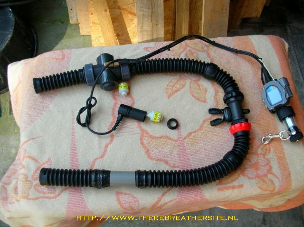
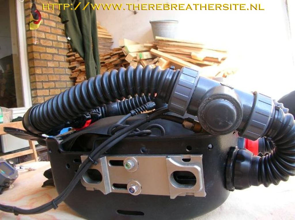
- Below you
can find some detailed pictures with some explanation on certain
details.
-
|
-
e
|
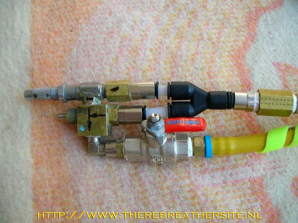
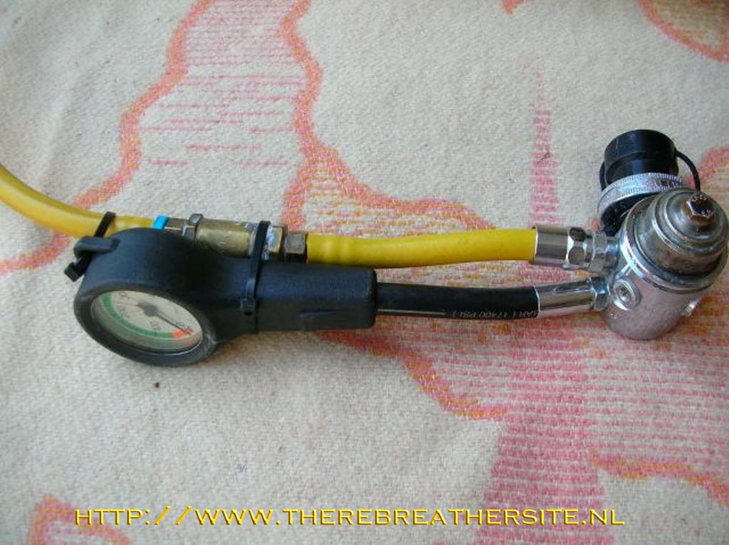
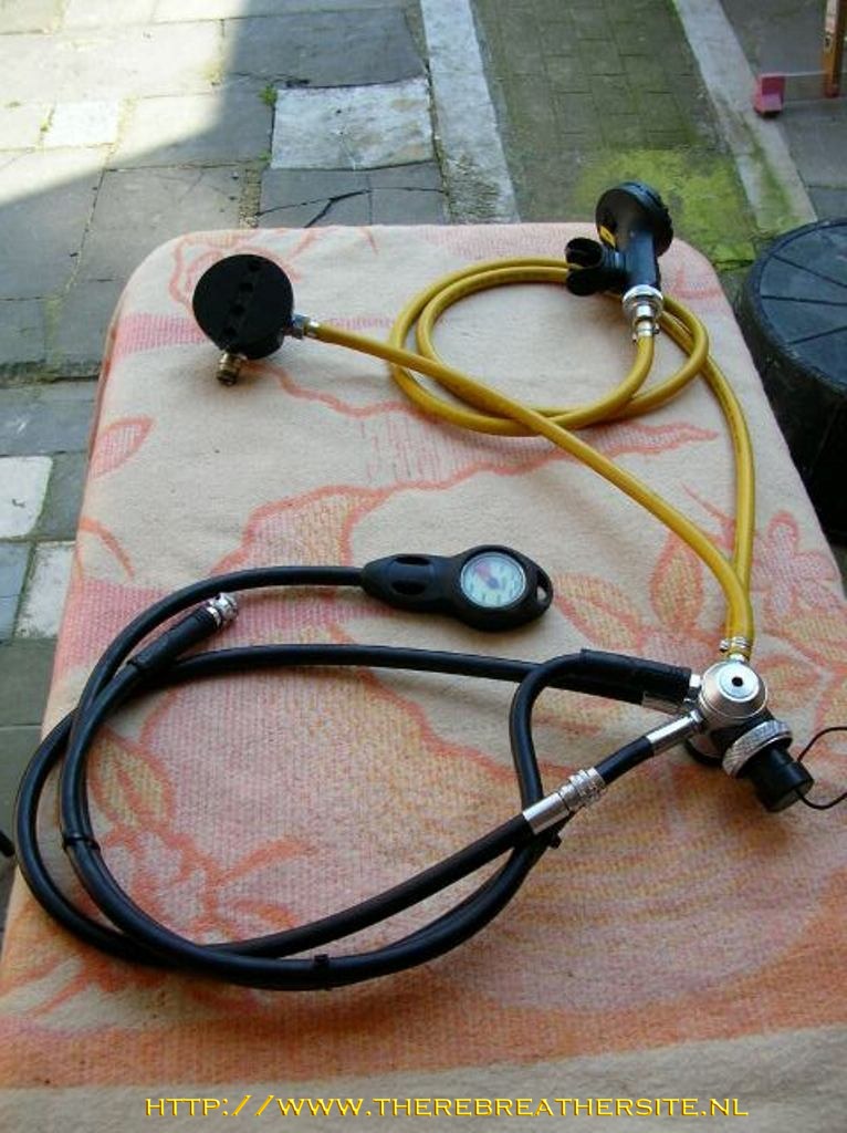
This is the
oxygen injection system, O² is injected through a Swagelock needle
valve, manual bypass is done through a Clippard Minimatics 2 way
valve (converted to 3 way by drilling an additional hole opposite to
the threaded outlet port).
|
-
|
-
|
- Just
before the shut off valve , is a 1/8-1/4 brass nipple which I
plugged on the inside by silver soldering a brass bar. At first
I drilled a 0.35 mm hole to meet the 8l/m manual bypass feed as
is used by Kerry.
- Well, I
found that on the deeper dives it took a while to get the PPO²
to level (1.3-1.4). So, I re drilled the
- Hole
with a 0.6mm drill and suits me fine now. At 40m I only need 2
short bursts to bring the PPO² to level. (I could measure the
bypass flow rate if required by someone)
-
- I also
fitted the Swagelock in line 15micron filter just after the O² 1st
stage as well as the O² gauge.
- During
a dive, you don’t look at the gauge anyway, so why put it over
your shoulder… another hose
- Hanging
around…
-
|
-
|
-
|
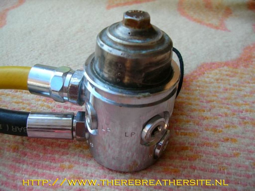
- One thing I
would like to mention… I got a bit scared reading all the different
warnings regarding the depth compensation on the O² 1stage regulator.
Well, I had a Poseidon Jetstream, which I like a lot, so had to look for
closing off the ambient pressure above the diaphragm. Here is my
solution:
-
|
|
 |
| |
- I soldered a
6mm SS bolt in the end cap where normally the hex. The hole is for
adjusting the intermediate pressure.
I also soldered the end cap to the diaphragm cap!
- By doing so, it
is easier for the annual maintenance. No sealant should be removed which
is a hell of a job!
- Of coarse one
would say, yes but now you can’t adjust the intermediate pressure by
Allen key..
- Yes, but I
adjusted the intermediate pressure by placing a SS washer above the
spring and gave me
- 9.5 bar!!
- Adjusting the
O² flow can easily be altered through the Swagelock needle valve.
-
- The point where
I inject the O², is in the original bypass valve. I used an original
orifice
- and removed
both the Rubin flow restrictors. The plastic tubes I leave in
place.
-
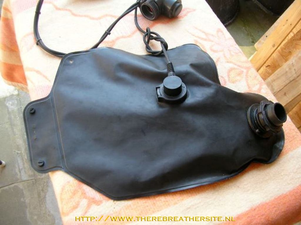
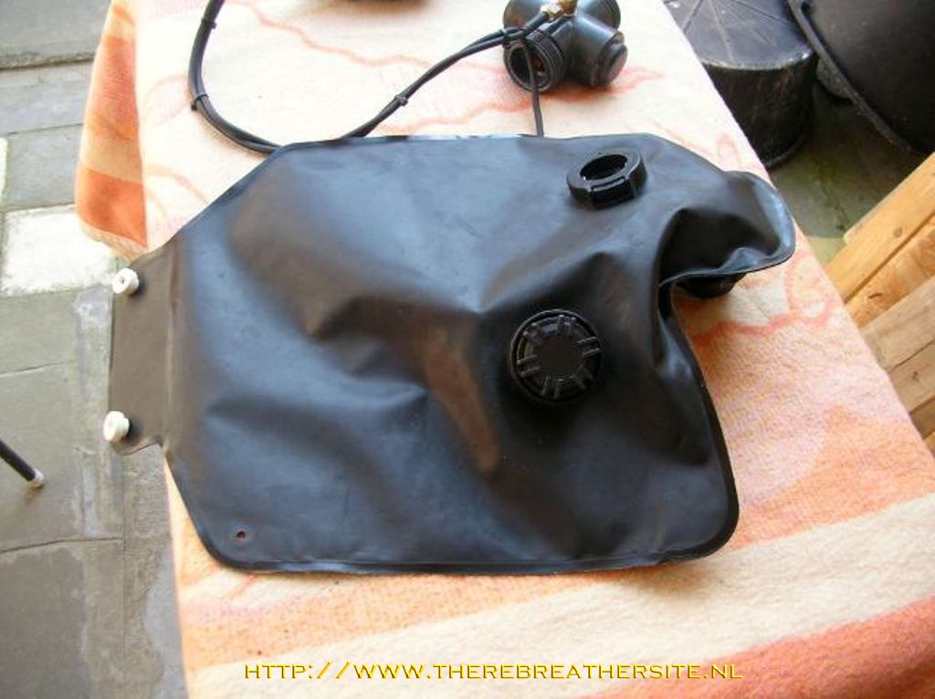
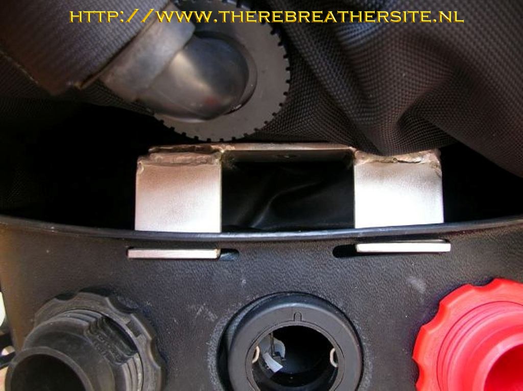
- The original
bypass was moved to where the OPV was fitted. Then the OPV was moved to
where the
- Original
P-connector on the back side of the inhalation lung. (Normally Plugged).
-
- The OPV manual
function had to be removed and was easily done (after opening the valve)
by fitting two "of the shelf" O-rings.
-
- So, no
additional holes had to be made in either breathing bag!!
-
|
|
 |
| |
|
 |
| |
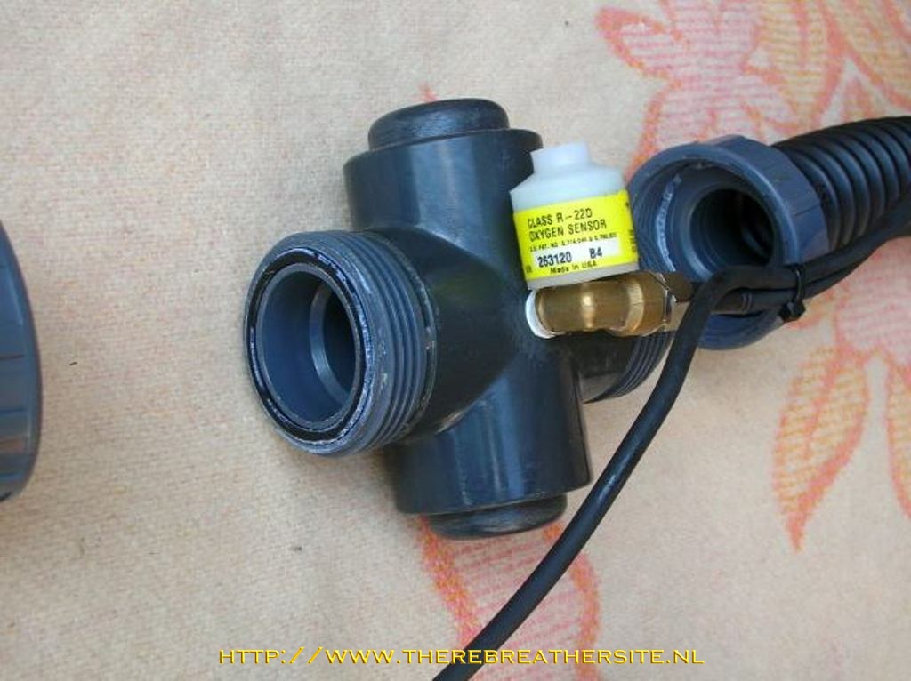
- For the PPO²
monitoring I use MY VR3 with O² sensor which fits in the P-connector
where normally the bypass valve is fitted.
-
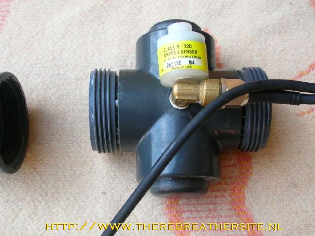
- The second
sensor was fitted using a PVC HP cross : (Michel Urbani design)
|
-
|
|
-
|
|
This means that very easily a second (so 3 in total) O² sensor can be added
in the inhale side.
I
will add a 2nd sensor in this cross at a later stage. |
| |
|
| |
|
 |
| |
|
 |
| |
- The PVC cross
was a little bit shortened as well as the standard screw fittings using
a lathe.
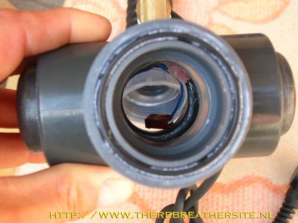
- When fitting
the cable through a cable gland and in my case an elbow, a friend of me
pointed out that he had had a lot of trouble with water coming in.. He
advised to cut the wires (4 in my case) solder them independently
together, feed them through the cable gland (making sure the soldering
connections don’t touch each other, not easy… and fill the whole with
epoxy resin..
-
- If one looks at
the Delta P oxygen cell holder for Dräger users, you can see they did
the same !! (or they were first!!)
-
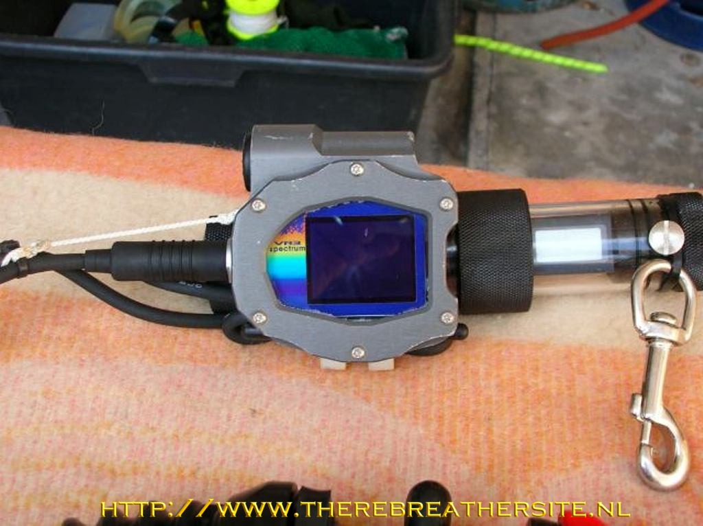
- The second PPO²
display is fitted in a Marc Munroe Lexan tube and end caps purchased
from Tecme.
-
|
|
 |
| |
|
 |
| |
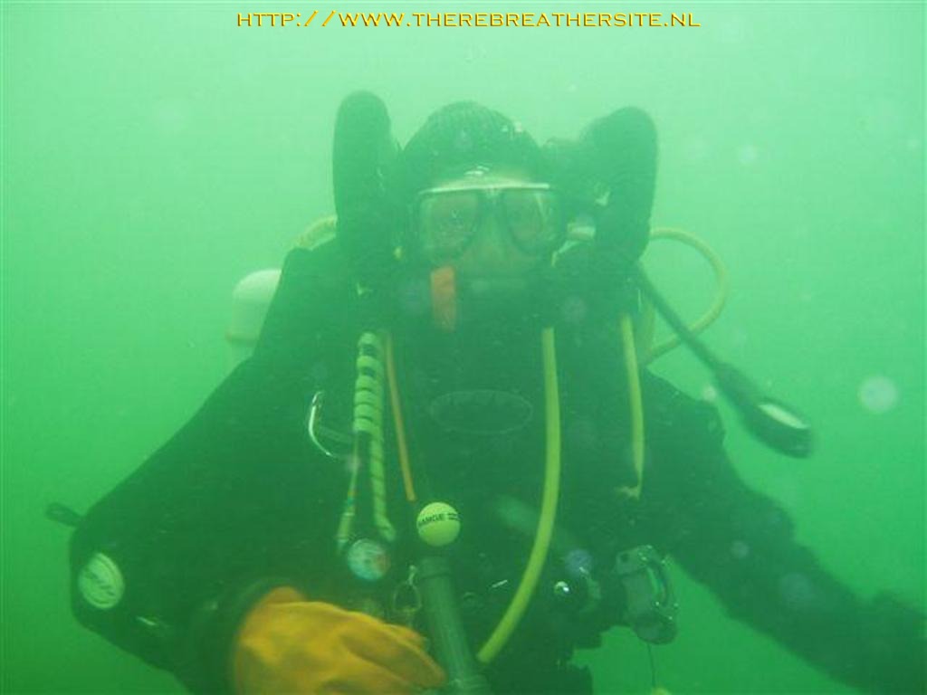
- I fitted the
VR3 and 2nd PPO² display together and that works very fine
for me. It just hangs close to my belly and is very easily spotted
looking down. I like this way since I have nothing fitted to my arms and
hands.
- This is a very
nice feature when diving wrecks on the North Sea!! (cfr my wife: my
second home!)
-
- That 2nd
display has a very nice feature…
- audible alarm
if PPO² drops below 0.35 or is above 1.6 bar (Hmmm I like it).
-
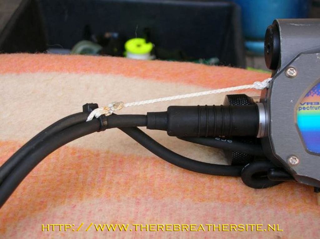
- I once , while
struggling with a huge conger (against my will ;)) had my sensor
connector pulled out off my VR3. Recently I read that another Kiss
Dolphin diver Kim Meiniche had similar problems.
- Therefore, I
fitted a small rope on the cable tie to the little groove on the VR3
where normally the blind plug was strapped on.
-
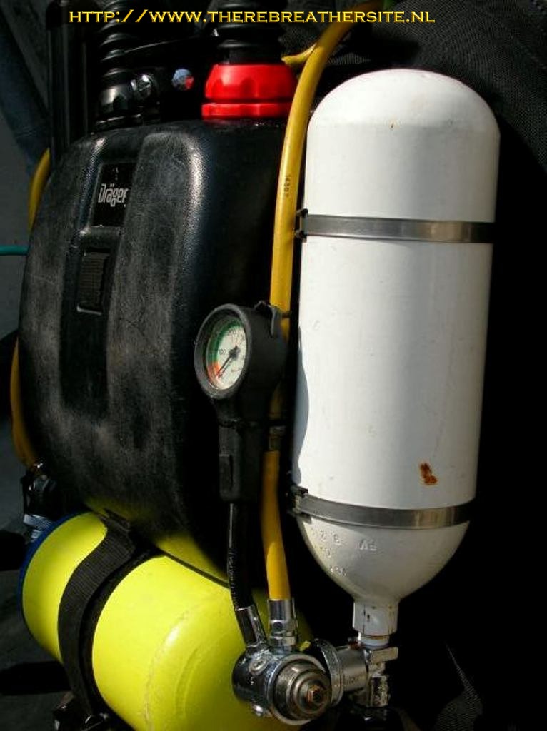
- Diluent
addition is done through a 4 ltr-200bar cylinder, a regular 1stage
regulator and using the
- Original Dräger
bypass. Therefore you need to remove the original spring and replace it
with another
- One with same
length but less tension. I had some trouble finding one, but finally
found one in an old
-
Inflator. (8 mbar opening pressure, to be tested !!)
-
|
|
 |
| |
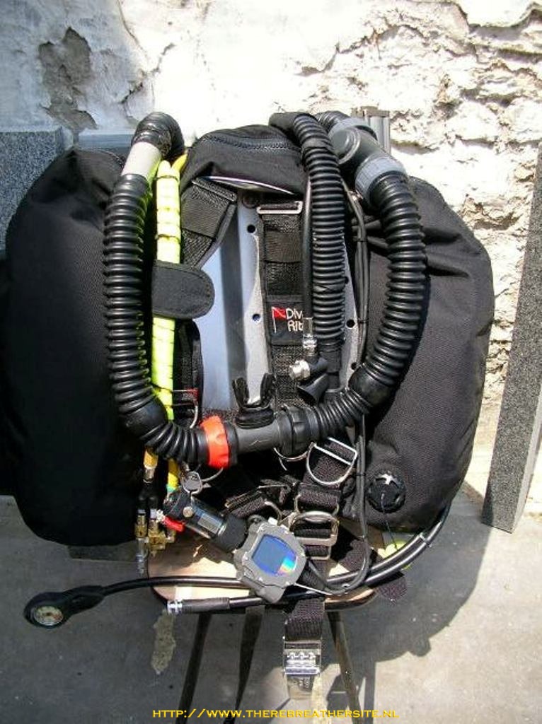
|
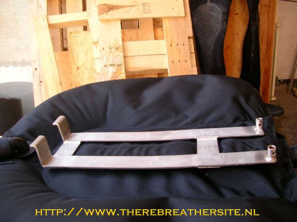
At
last I wanted to fit a wing instead of the original BC, but didn’t want to
use a wrench for removing
The wing. I came up with a nice solution : |
| |
|
 |
| |
|
 |
-
|
|
 |
| |
|
 |
| |
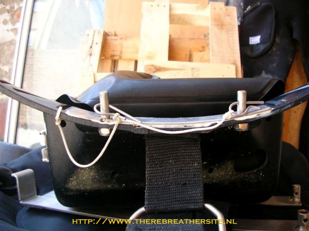
- For removing
the wing, I just have to pull 2 SS clips and lift the wing up. This is a
very quick and nice feature for working on the RB.. for example with
problems on the negative or positive pressure test !!
-
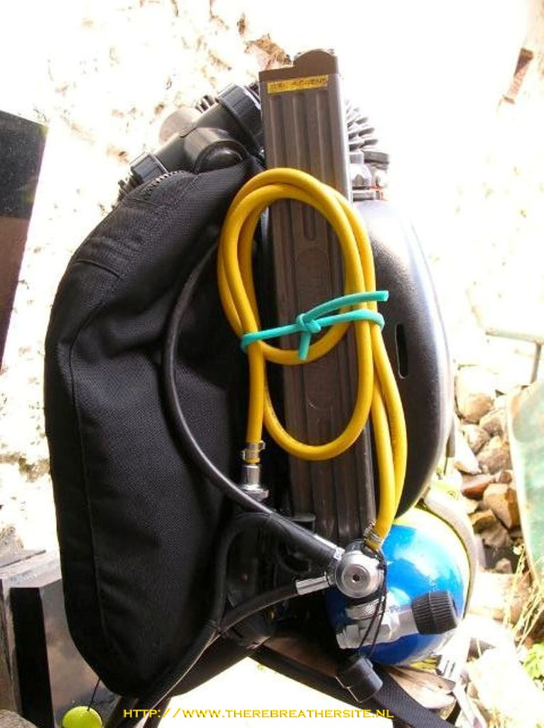
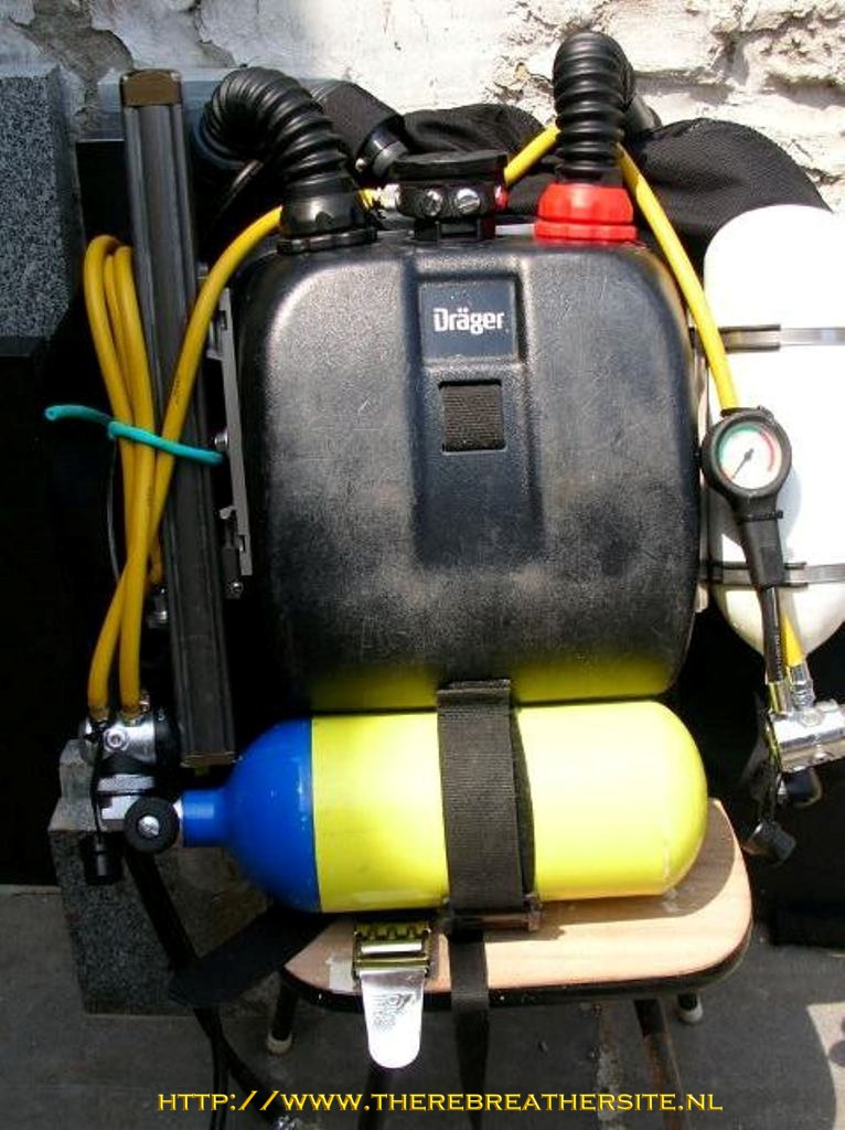
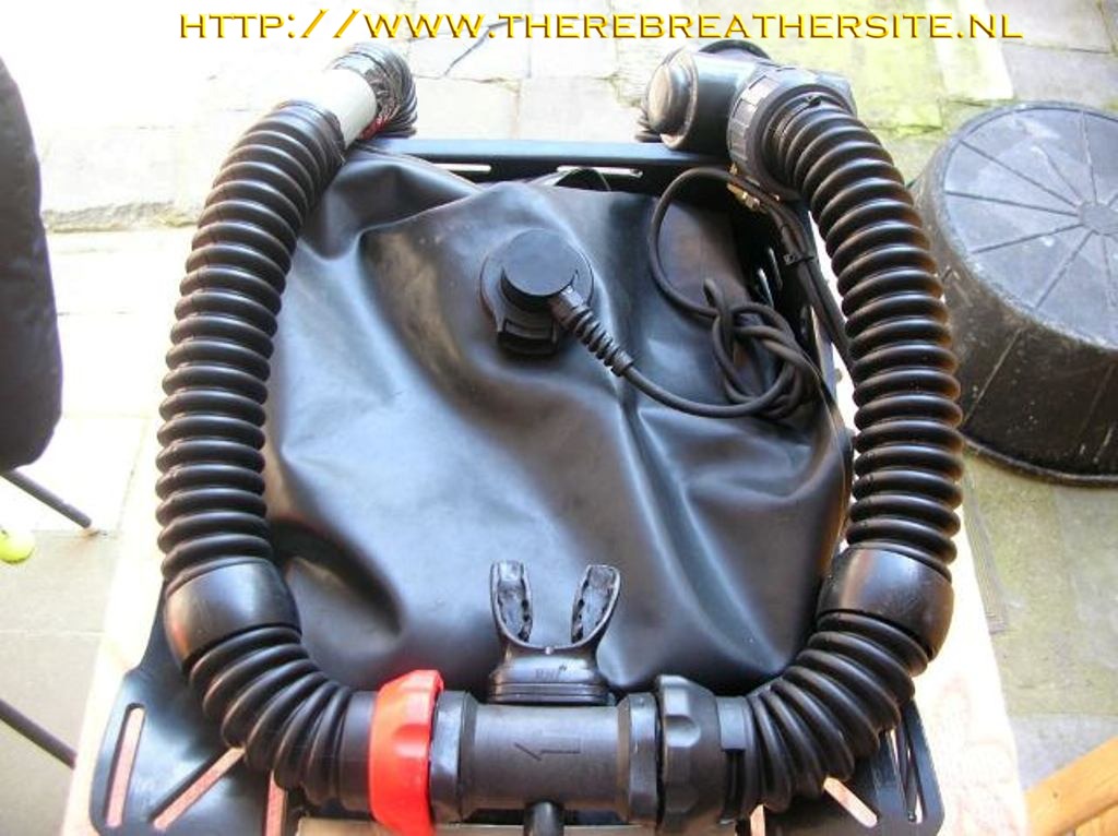
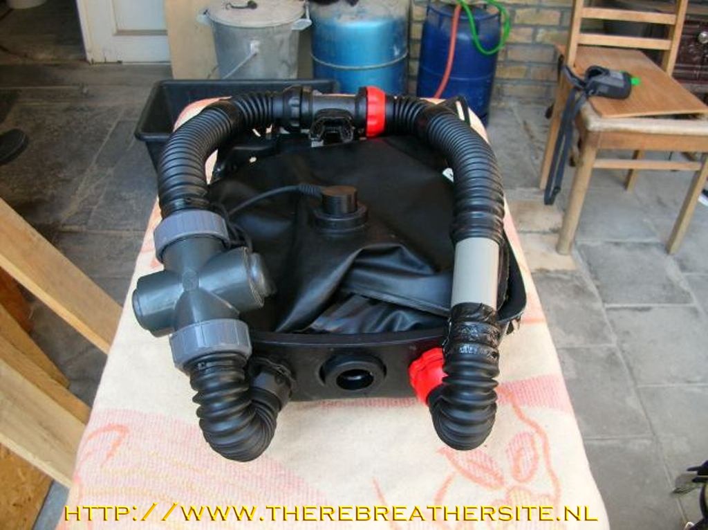
- Below are some
pictures with different views of my “second wife”
|
| |
|
 |
| |
|
 |
| |
|
 |
| |
|
 |
| |
|
 |
| |
|
 |
| |
|
 |
| |
- Well, that
was it! I am very happy that Janwillem Bech allowed me these pages
to be put or accessed on his website.
-
-
- Without
this help I really wouldn’t have been able to modify my Dolphin.
-
- Thanks to
all of you and safe diving.
-
-
Oostende, Belgium
-
-
Special thanks to: JanWillem Bech
-
Kerry McKenzie
-
Paul Raeymakers
-
Michel Urbani
-
-
|
|
page created on 29 June
2005 |
|
|